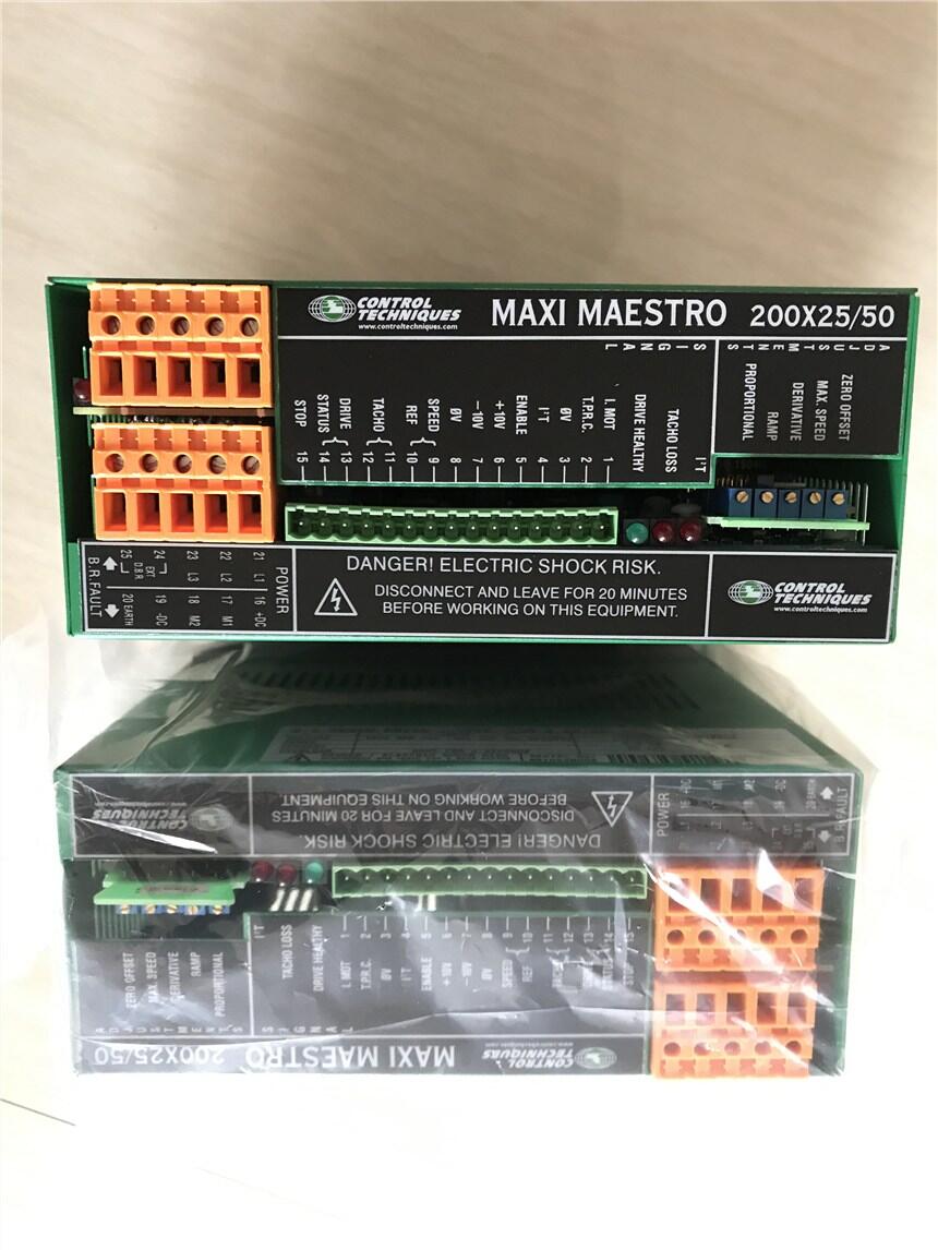
Product Inbation
2.1 Features
2.1.1 Selectable options
Speed control with armature feedback
Speed control with tachogenerator feedback
Acceleration and deceleration ramps
Tachogenerator loss-protection
2.1.2 Adjustments
Full-scale speed
Current limit
Dynamic gain
Derivative b
Reference speed offset compensation
Ramp gradient
2.1.3 Diagnostic functions
I 2 t LED indication
LED indication of tachogenerator loss
Drive NORMAL LED indication
Digital output indicates drive status
Digital output indicates I 2 t limit
Analog output indicates motor current
Analog output indicates TPRC
2.2 Data
2.2.1 Analog speed reference b
±10V (10k? b impedance)
2.2.2 Error amplifier temperature drift
1.3 μV / °C
2.2.3 Tachogenerator feedback control range
1 to 5000 rpm
2.2.4 Minimum tachogenerator signal at maximum speed
5V (To ensure the drive reaches maximum speed with a 10V reference)
2.2.5 Armature feedback control range
150 to 3000 rpm
2.2.6 Ambient temperature
Operating temperature range: –10°C (50°F) to +50°C (122°F)
2.2.7 AC supply
Table 2.1 Minimum supply voltage – three phase
Tolerance:
Midi-Maestro: +10% -35%
Maxi-Maestro: +20% -35%
Tolerance:
Midi-Maestro: +10% -35%
When the drive is operated on a single-phase supply, the characteristics of the drive are
modified as follows:
I NOM –25%
I PEAK –25%
Voltage to the motor –25%
2.2.8 Power cables
Midi Maestro 2.5 mm 2 (AWG 14)
Maxi Maestro 4.0 mm 2 (AWG 10)
2.2.9 Signal wiring
0.5mm 2 (AWG 20)
2.2.11 Current tolerance
±10%
2.2.12 Braking resistor data
Midi-Maestro
Internal Braking resistor - Fitted as Standard
